what are you looking for?

The home solar photovoltaic power generation system is a small distributed photovoltaic system. Therefore, the actual situation should be fully considered in the design process. Generally, it should follow the principle of economic application, high reliability, firm and durable, easy to maintain, and fully consider the influence of geography and climate environment.
Installation location selection
The location of the home distributed PV system can generally be selected on the roof or open space of the house. The conditions to be considered are the usable area, the structure of the house and the load-bearing requirements, the ground conditions and the meteorological and hydrological conditions. If you choose to install on your own roof, the load-bearing capacity of the roof must be greater than 20kg/m2.
If the house beam is a wooden structure, do not consider it. The photovoltaic system has a service life of 25 years. The wooden house beam is perishable. It is not recommended to install it. If a solar home solar power station is built on the roof of a herringbone structure, the optimal tilt angle cannot be designed like the ground power station, and the front and rear occlusion spacing is considered. In order to facilitate the combination of photovoltaic modules and roofs, the brackets are generally laid directly on the roof, the north hemisphere is paved to the south, and the southern hemisphere is paved to the north, so that the light energy can be utilized most efficiently. The bracket and the roof are connected by a clamp, and the battery assembly is then mounted on the bracket. This method is not only beautiful, but also maximizes roof area utilization, as shown in Figure 2.

In the construction of solar home solar power stations on flat roof structures, it is necessary to erect photovoltaic supports and design optimal inclination and front and rear spacing of components, as shown in Figure 3.

If you choose to install it on your own open space, you can use anchor piles and concrete strip bases as the foundation of the support. See Figure 4 and figure which ones need to be considered from the geological conditions and costs. In addition, the design of the foundation strength of the bracket should be based on local meteorological conditions.

It should be noted that considering the thermal expansion and contraction effect of the component, the spacing between the upper, lower, left and right components during installation is preferably about 3 cm.
Household distributed photovoltaic system design
Photovoltaic module
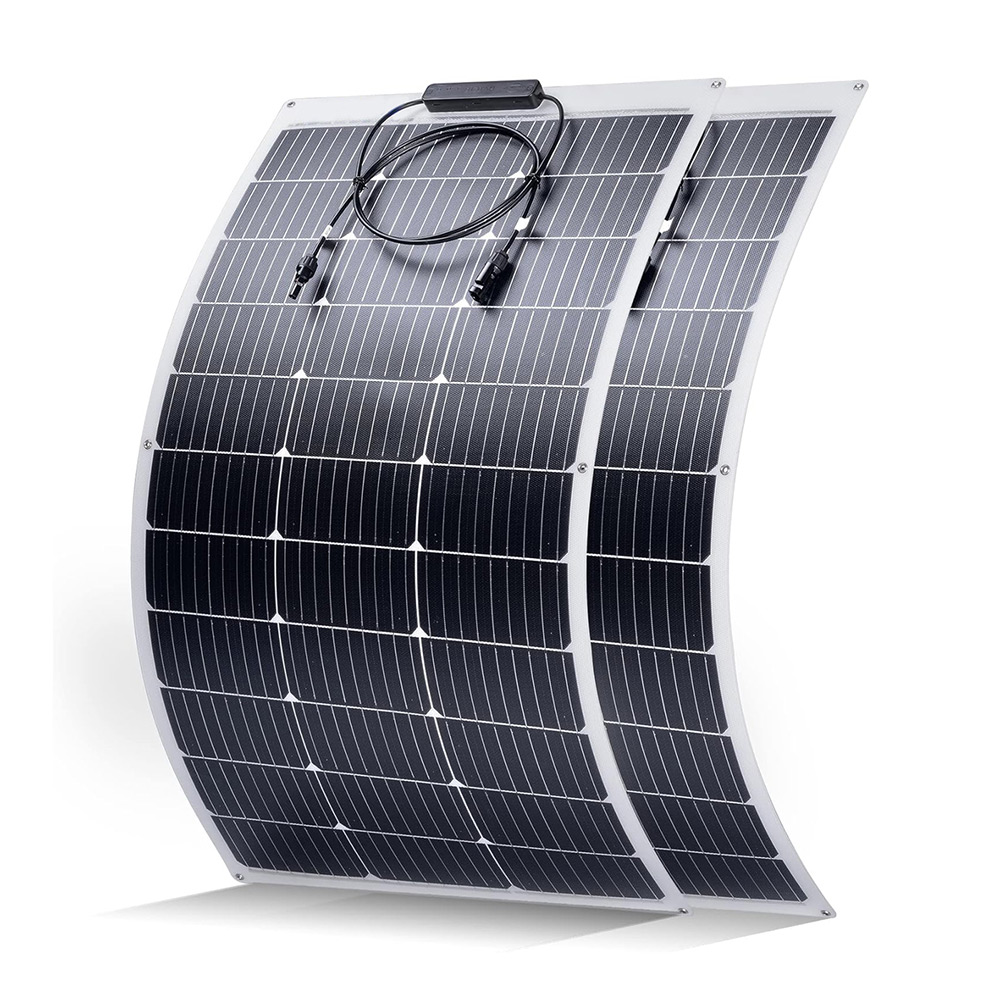
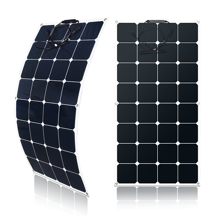
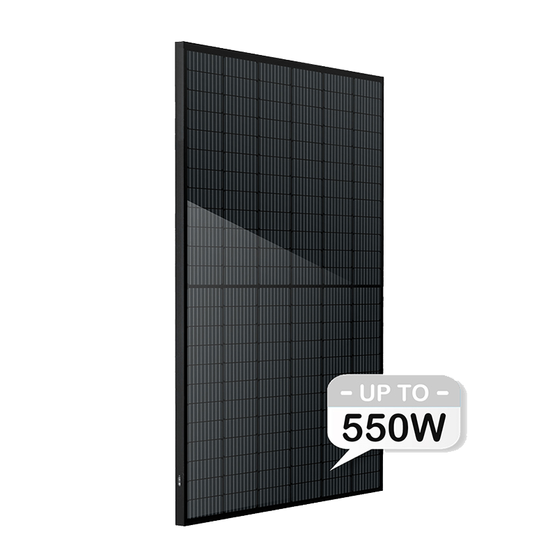
The two solar panels currently in use are monocrystalline silicon and polycrystalline silicon solar cell modules. The current mainstream component is a 250Wp polysilicon solar module.
Combined with the current photovoltaic power generation technology, the annual power generation of the five-category area of 1kWp polycrystalline silicon solar modules is roughly as follows
Users can choose the installed scale according to the installation location of the system and their annual electricity consumption.
PV module array mounting orientation and angle
If the installation location is flat, calculate the dip of the PV bracket, with the northern hemisphere facing south and the southern hemisphere opposite. Considering that the tracking system can improve the system efficiency, but needs maintenance, and will increase the failure rate, combined with cost, practicality and other factors, the family distributed photovoltaic system uses a fixed photovoltaic square array is better. The data obtained from the weather station are the amount of solar radiation on the horizontal plane, and the amount of radiation that needs to be converted into the inclined surface of the photovoltaic array can be used to calculate the power generation.
For a PV array fixedly mounted at a certain angle of inclination, the received solar radiation energy is related to the dip angle. The simpler formula for calculating the radiation amount is:
Rβ=S*[sin(α+β)/sinα]+D
Where: Rβ—the total amount of solar radiation on the surface of the tilted PV array S—the amount of direct solar radiation on the horizontal plane D—the amount of scattered radiation α—the solar elevation angle β at noon—the PV array tilt angle
According to the solar radiation data provided by the local meteorological bureau, according to the above formula, the amount of solar radiation on different inclined surfaces can be calculated to determine the installation angle of the solar photovoltaic array. A lot of use now is to use Rescreen software to analyze the irradiance of different inclination angles on the slope, and then calculate the annual power generation of different inclination angles according to the relevant parameters of the components, and finally take the corresponding inclination angle of the maximum annual power generation.
Solar cell array spacing calculation
Calculate the minimum spacing D when the solar array sub-arrays are installed before and after.
General determination principle: The solar array square array should not be blocked from 9:00 am to 3:00 pm on the winter solstice day.
Grid-connected inverter selection
Selection
Grid-connected inverters are mainly divided into three categories: high-frequency transformer type, low-frequency transformer type and transformerless type. According to the designed system and the specific requirements of the owner, the type of transformer is mainly considered from the aspects of safety and efficiency.
The household distributed photovoltaic system is a small system, which does not require high technical indicators. When the inverter does not have an isolation transformer, the energy conversion efficiency is higher. Combined with the cost and other factors, it is more reasonable to select a transformerless type.
Capacity matching design
In the grid-connected system design, the battery array is required to match the power capacity of the connected inverter. The general design idea is: component nominal power * component serial number * component parallel number = battery array power in capacity design, grid-connected The maximum input power of the transformer should be approximately equal to the power of the battery array, and the maximum utilization of the inverter resources has been achieved.
MPP voltage range matches battery pack voltage
According to the output characteristics of the solar cell, the battery component has a maximum power output point, and the grid-connected inverter has the function of automatically tracking the maximum power point within the characteristic input voltage range, so the output voltage of the battery array should be within the inverter MPP voltage range. .
Battery pack voltage * component series number = battery array voltage
The general design idea is that the nominal voltage of the battery array is approximately equal to the middle value of the MPP voltage of the grid-connected inverter, so that the best effect of the MPPT can be achieved.
Maximum input current matches battery pack current
The maximum output current of the battery array should be less than the maximum input current of the inverter. In order to reduce the DC loss during the component-to-inverter process and to prevent overheating or electrical damage to the inverter due to excessive current, the difference between the maximum input current value of the inverter and the current value of the battery array should be as large as possible.
Battery component short circuit current * component parallel number = battery array maximum output current
Conversion efficiency
The efficiency of the grid-connected inverter is generally divided into maximum efficiency and European efficiency. The European efficiency corrected by the weighting factor is more scientific. If the inverter meets other conditions, the conversion efficiency should be as high as possible.
Access plan
This solution is mainly applicable to household solar power station systems for self-sufficient/maintenance Internet access (access to the customer's power grid), see figure. First, a miniature circuit breaker and a smart energy meter with two-way metering function need to be installed in the household indoor distribution box. Through the air switch control access to the power grid, increase an obvious breaking point, meet the automatic disconnection, blocking function, low voltage power failure requirements, in line with the safe operation requirements of the grid; the accuracy of the smart meter with two-way metering function is not less than 2.0 As a measurement gateway.
Secondly, it is necessary to install a meter with an accuracy of not less than 2.0 in the grid-connected AC distribution box.
Selection of photovoltaic cables
The choice of cables in photovoltaic systems mainly considers the following factors:
Thermal and flame retardant properties of cables;
The cable is protected from moisture and light;
Cable laying method;
Type of cable core (copper core, aluminum core);
Cable size specifications. The connection between the different components in the PV system, the choice of cables is different because of the environment and requirements
The technical requirements for the different connection sections are listed below:
1) Connection between components and components: must be tested, heat-resistant 90 ° C, acid-proof, chemical-proof, moisture-proof, anti-exposure. The cable is used outdoors and exposed directly to the sun. The DC part of the PV system should be made of a cable that is resistant to oxidation, high temperature and UV.
2) The connection between the inside of the square matrix and the square matrix: it can be opened or buried underground, requiring moisture and sun exposure. It is recommended to install the tube and the tube must be heat resistant to 90 °C.
3) Wiring between square array and inverter: It must be tested, heat-resistant at 90 °C, anti-acid, anti-chemical, moisture-proof, anti-exposure. The cable is used outdoors and exposed directly to the sun. The DC part of the PV system should be made of a cable that is resistant to oxidation, high temperature and UV. Cable size specifications must follow the following principles:
1) For the connection of the AC load, the rated current of the selected cable is 1.25 times the maximum continuous current in the calculated cable. For the connection of the transformer, the rated current of the selected cable is 1.25 times the maximum continuous current in the calculated cable. The connection between the square matrix and the square matrix, the rated current of the cable is 1.56 times of the maximum continuous current in the calculated cable.
2) Consider the effect of temperature on the performance of the cable.
3) Consider the voltage drop not to exceed 2%.
4) Appropriate cable diameter selection is based on two factors, current strength and circuit voltage loss.
Lightning protection design
In order to ensure the safety and reliability of the photovoltaic grid-connected power generation system of this project, and to prevent the damage of system components caused by external factors such as lightning strikes and surges, the lightning protection grounding device of the system is indispensable. Solar home solar power stations are three-level lightning protection buildings. Lightning protection and grounding involve the following aspects:
1. Try to avoid the projection of the lightning rod falling on the PV module.
2, the ground wire is the key to lightning protection and lightning protection. Prevent lightning induction: Metal sheaths including equipment, racks, metal pipes and cables must be reliably grounded. Each metal object must be connected to the grounding trunk separately. It is not allowed to be connected to the grounding trunk after series connection.
Precautions
PV module maintenance precautions
To avoid arcing and electric shock, do not disconnect the electrical connections while working under load. The plugs must be kept dry and clean to ensure they are in good working order. Do not insert other metal objects into the connector or make electrical connections in any other way. Do not touch or operate the PV module with broken glass, frame detachment, and damaged backing plate unless the component is disconnected from the electrical connection and you are wearing personal protective equipment. Do not touch wet components.
Dangerous substances such as flammable liquids, gases and explosives are prohibited from being placed near PV modules.
In the event of a fire, even if the PV module is disconnected from the inverter, the PV module is partially or completely burnt, the system cable is broken or damaged, the PV module may continue to generate dangerous DC voltage. Therefore, in the event of a fire, try to stay away from the photovoltaic system until the corresponding measures are taken to ensure the safety of the PV system.
Please do not block the PV modules when the system is working, because the system performance and power generation will be significantly reduced when one or more PV modules are partially or completely blocked.
Do not step on or place heavy objects on the surface of the component to avoid cracking the battery.
After long-term operation of the PV module, dust or dirt will be deposited on the surface of the component, reducing the output power. It is recommended to perform component cleaning on a regular basis in the morning or in the afternoon (using a soft cloth), especially in areas where there is less precipitation and where there is more dust and sand. Be careful not to clean glass-broken PV modules or exposed cables to avoid danger.
When removing the surface area of the PV module, use a brush to gently remove the snow. It is not possible to remove frozen ice from the surface of the PV module with a hard object.
Inverter considerations
The inverters have been set up after completion, and non-professionals should not touch photovoltaic devices such as inverters.
Do not touch the heat sink of the inverter to avoid burns.
Do not place dangerous goods near the inverter.
It is not advisable to change the position of the inverter privately, since the installation design from FGET Solar at the time has taken into account the environmental factors that are suitable for the operation of the inverter. In particular, the inverter should not be placed in areas exposed to the sun or poorly ventilated.
It is forbidden to block the ventilation of the inverter.
Disconnect the inverter's AC or DC voltage sequence: first disconnect the AC voltage and then disconnect the DC voltage.
Regularly clean the dust on the inverter cabinet. It is best to use a vacuum cleaner or a soft brush when cleaning, and only use a dry tool to clean the inverter. If necessary, remove dirt from the vent hole to prevent excessive heat from being caused by dust, resulting in impaired inverter performance.
Choose reliable after-sales service
The installation of photovoltaic panels to the roof will not last less than 25 years. Whether it is a commercial or commercial roof distribution of several MW or a distributed power generation system of several KW, a reliable and perfect after-sales service system is particularly important.
How to ensure that the system generates electricity normally, it is recommended to pay attention to the following aspects:
First of all, the choice of equipment must be quality assurance, especially components and inverters. Don't use cheap and inferior equipment for the sake of cheapness. In this industry, the price is basically transparent. As the saying goes, one price is worth the price. No one is alive Lei Feng. In the daily business negotiations, there are often customers who propose that the price of a certain company is much lower. For such a situation, I can only advise the customer to seriously consider and carefully consider the choice of a trustworthy company.
Secondly, the design of the overall system solution and the professionalism of on-site installation should not be underestimated. In order to maximize the benefits, individual practitioners specially choose low-priced and inferior equipment to shoddy. In the process of on-site installation, they are also eager to make progress, ignoring the details that should be paid attention to during installation. How can such a power generation system withstand years of testing?
 Monday -Sunday: 8:00 - 24:00
 No.13 Shang Zhen East RD., Taihe Town Baiyun Area, Guangzhou China
 info@futuregreenbattery.com